
Have you taken steps to plan your house design? Have you learned architecture terminologies that are commonly mentioned during the design process? While waiting for the design to wrap by the architect, it’s no harm to learn about these drawing lists for house design planning, along with the functionalities. The reason is each technical drawing has different benefits.
The following elaborates a list of house design planning and the functions to give you extra knowledge regarding the functions of each technical drawing made by Emporio Architect.
A. Architectural Technical Drawing
1. Site Plan
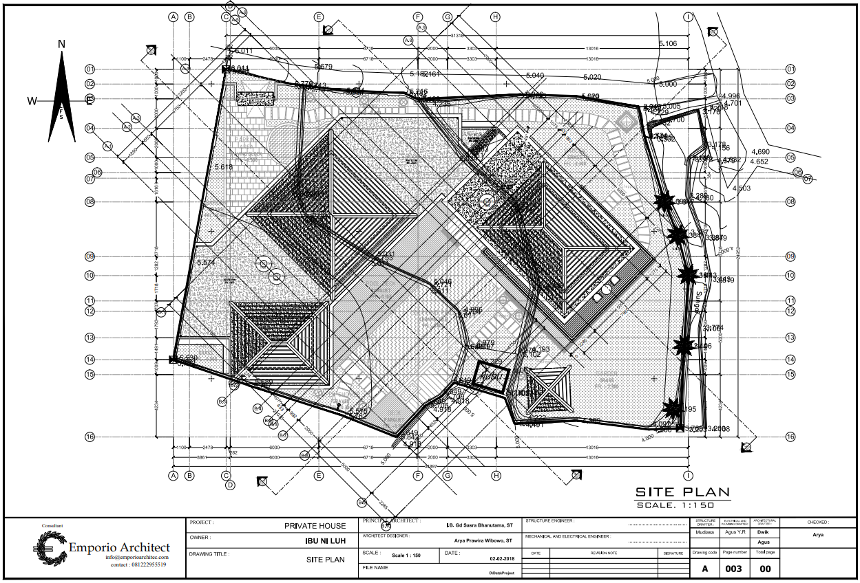
Site plan drawing can usually be seen on the initial page of the technical drawing. The Site Plan elaborates in general about various supporting elements, which includes the shape of the roof, the land size and boundaries, the ground floor layout, road, and trees position, along with the surrounding public facilities with its scale, dimension, cardinal points, line section, and other symbols.
Through the site plan, the rough idea of the complete design can be seen in a less detailed elaboration. In simpler words, this site plan looks like a sky view building portrait taken by a drone camera.
2. Each Floor Plan
.png)
The floor Plan elaborates the circulation, spatial arrangement, furniture placement, leveling, openings, and the name of each room on each floor on the building design. If the building is planned to have 4 floors, then the layout will include 4 drawings divided into a plan of the basement, ground floor, second floor, and so on.
3. Roof Plan
.png)
Not too different from the floor plan, the roof plan elaborates the roof plan and shape that will be applied. At first glance, the roof plan looks similar to the site plan drawing.
4. The Display (Front, Right Side, Left Side, and Rear View)
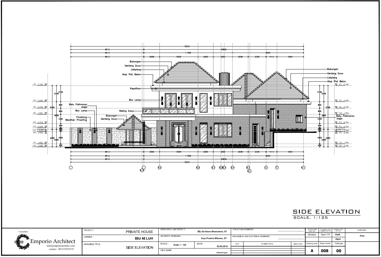
The display plan elaborates the view and the exterior look of the building. It starts from the dimension, proportion, architecture style, shape, color, and material that will be applied, along with the elevation of the building.
The view plan previews the sight from every side, including the front view, the left side, the right side, and the rear view of the building.
5. Sections (A-A, B-B, C-C, D-D)
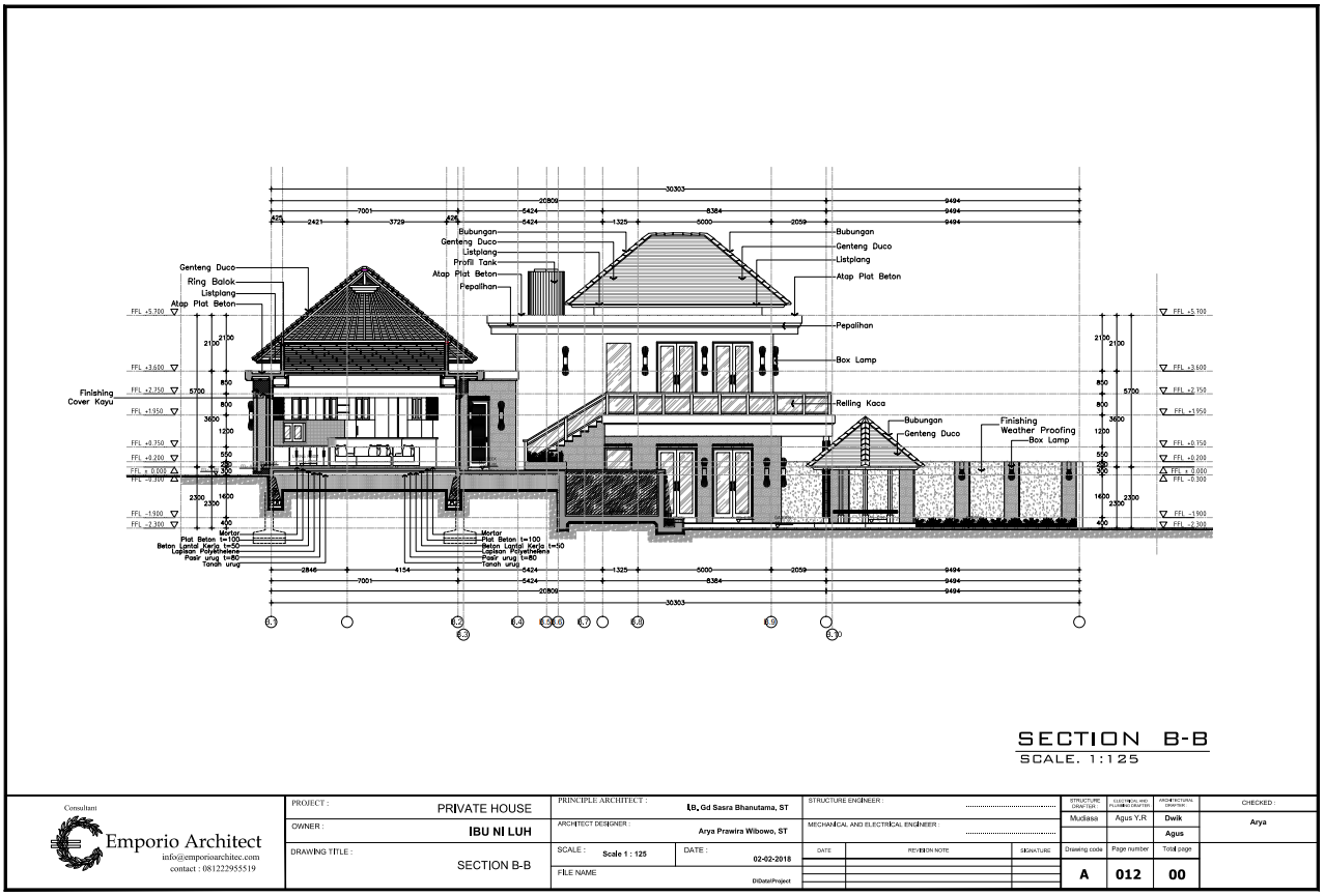
Section drawing looks like a building drawing that has been sliced and elaborates the composed material layers, along with the construction and structure from the roof all the way to its foundation. These sections also elaborate the proportion and elevation of the building with the interior display included.
In the section drawing, everything that is included in the section will be sliced to expose the inside part. There are as many section lines in the technical drawing book as there are section lines on the layout plan. Generally, there are sections A-A, B-B, C-C, and D-D.
6. Door & Window Frame Plans
Door & Window Frame Plans elaborate floor layouts with symbols that refer to the frame positioning or opening on a certain floor. The symbols on these frame plans show the type of frames that will be used and will be clarified with a detailed drawing.
Similar to the previous step, each floor of the building has a different frame plan drawing. As a result, there will be door & window frame plans on the ground floor and so on up to the roof.
7. Frame Details
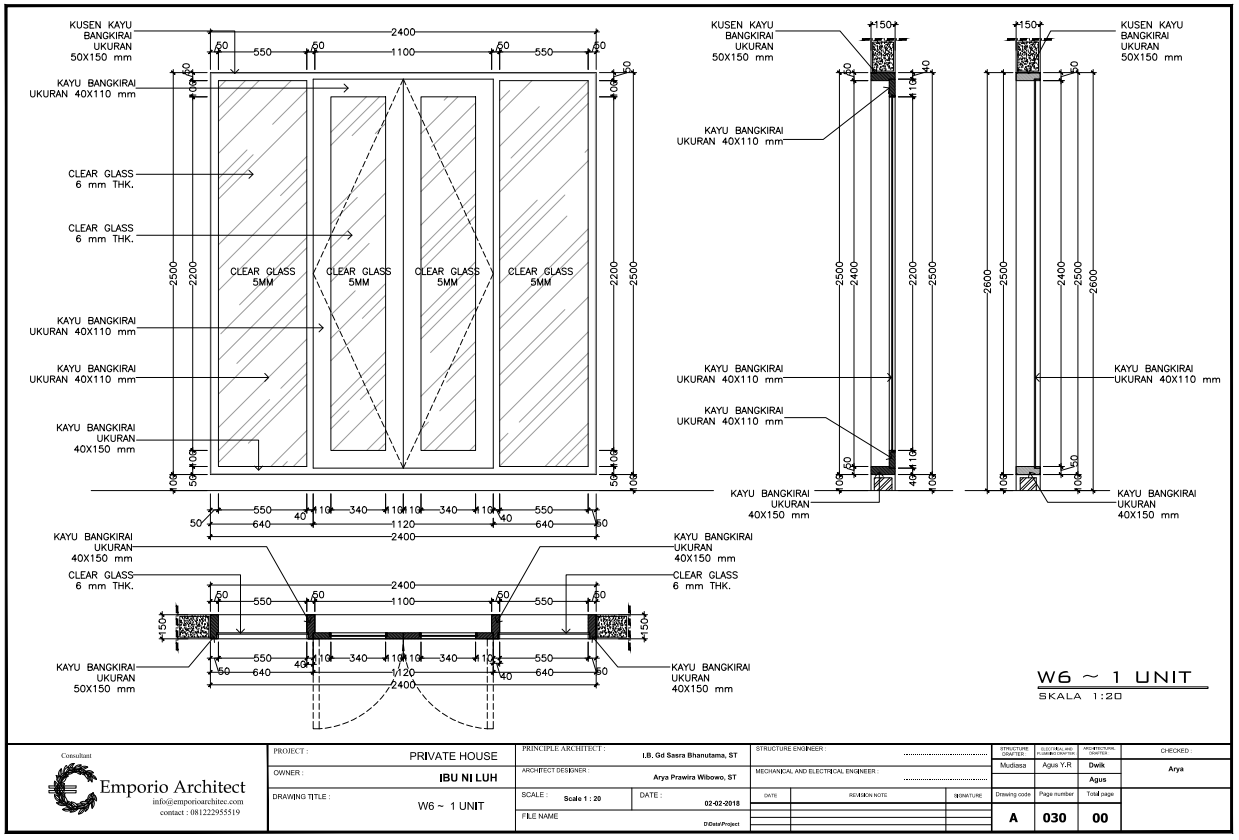
This plan is the more in-depth drawings of windows and door frames, which are the more detailed versions of the door & window frame plans. Detailed drawing of windows & door frames elaborates the layout, view, and sections of windows & door frames with the size, type, and name of the material used.
8. Ceiling Plan (of Each Floor)
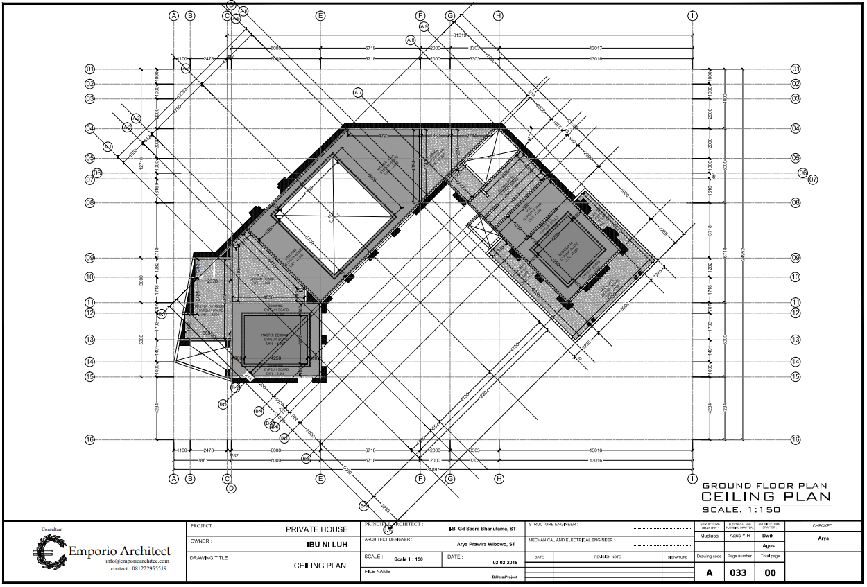
The ceiling plan elaborates the placement of ceiling components on each floor, along with the size, scale, and name of the materials. The ceiling plan includes a sheet of each floor’s ceiling plan.
9. Floor Pattern Plan (of Each Floor)
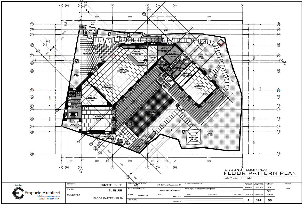
To match the name, the floor pattern plan elaborates the floor covers, along with the composition, type, dimension, material color used, and the elevation of the floor area. The plan drawing includes a sheet of the plan for each floor of the building.
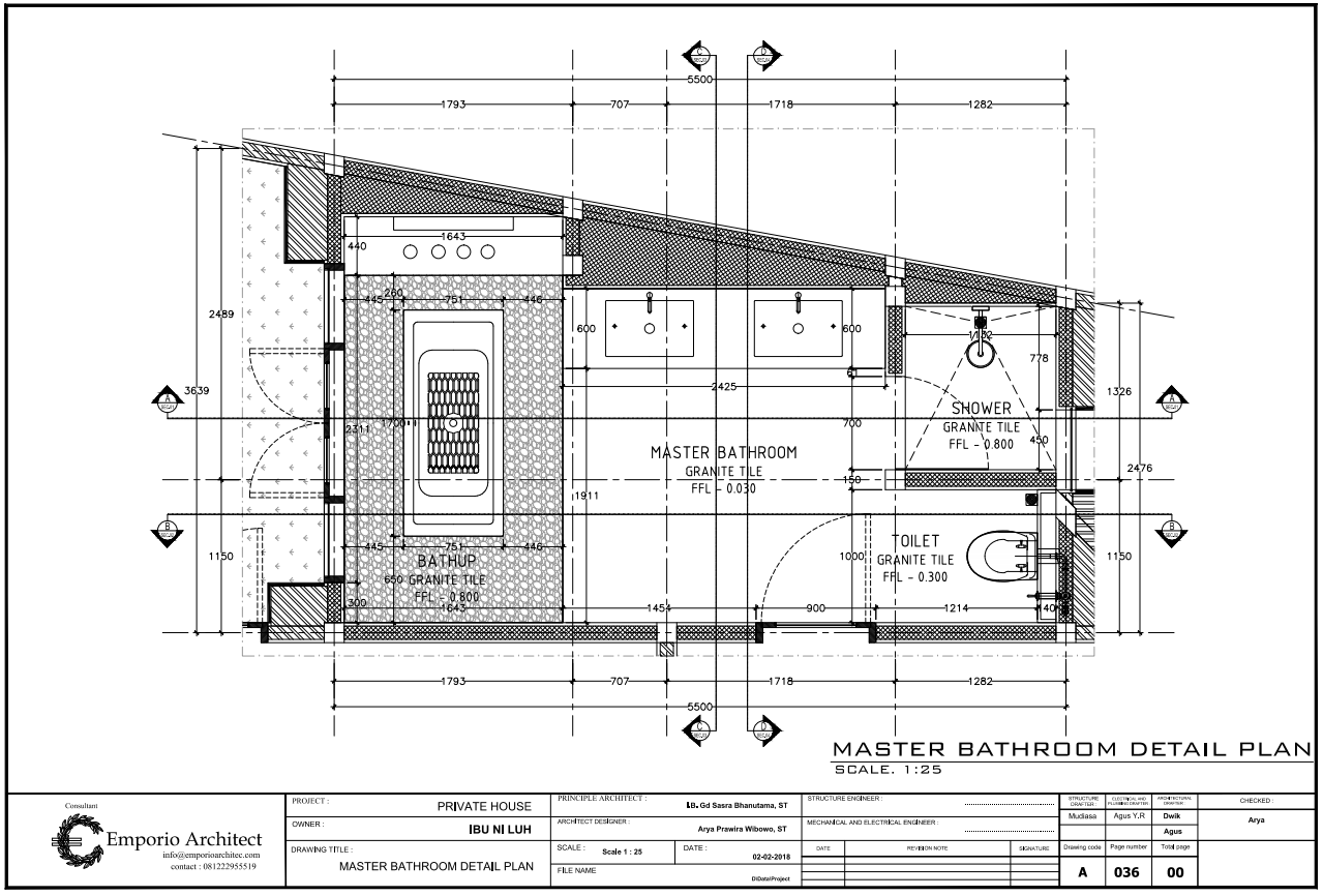
10. Master Bathroom Plan
.png)
The master bathroom plan elaborates several components that are similar to the floor plan, but it only covers the master bathroom.
11. Master Bathroom Plan Details (Section A-A, B-B, C-C, D-D)
The master bathroom plan details elaborate the A-A, B-B, C-C, and D-D sections of the master bathroom on a larger scale, which creates a clearer image of the dimension, sectioning line, material type, floor elevation, placement and view, structure, and construction, furniture, and the display of the master bathroom from the coiling to its foundation or floor.
12. Stairs Plan of Each Floor
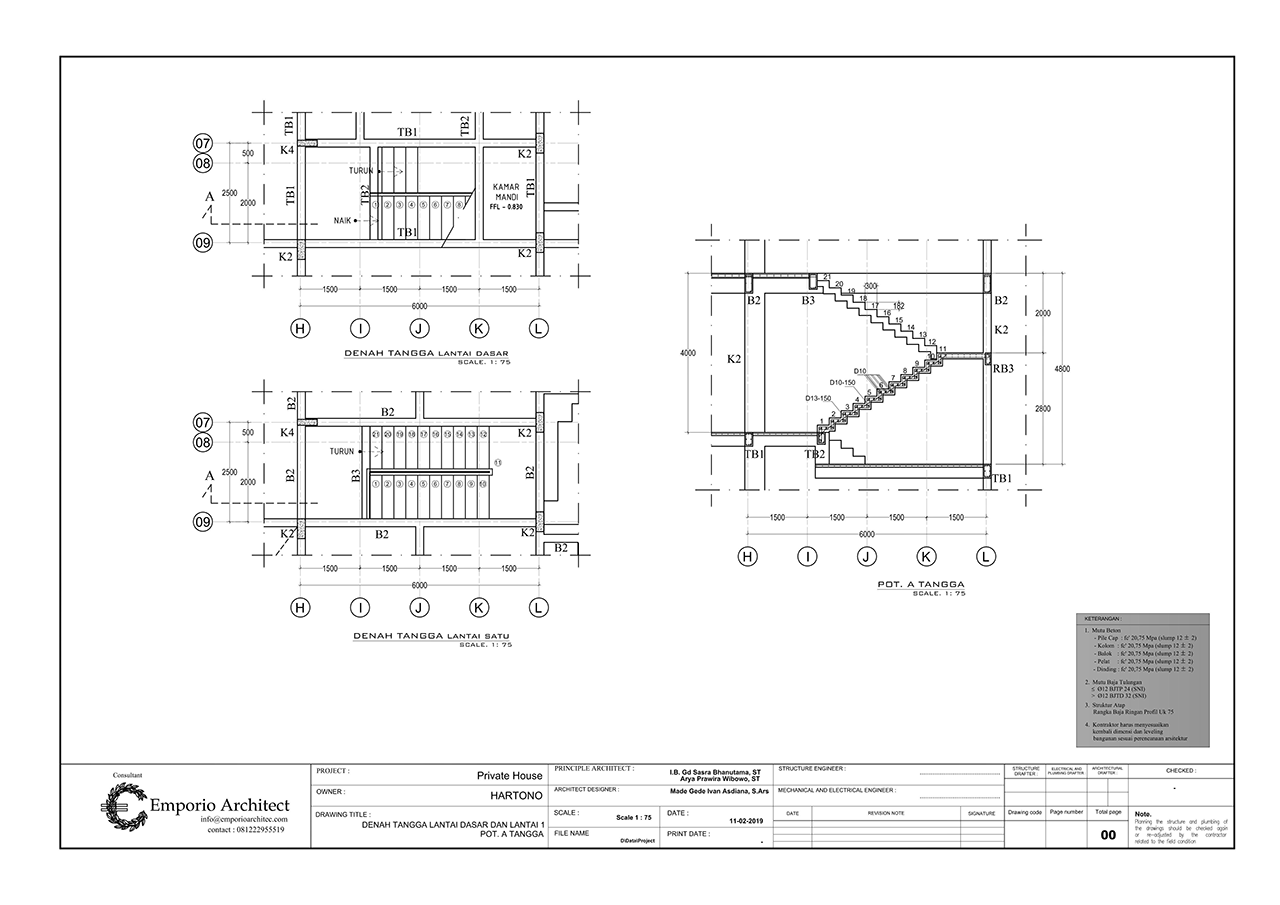
The stairs plan of each floor elaborates the plan, shape, and display of each stair on a larger scale. This drawing contains information about the shape and elevation of each stair-step.
13. Stairs Plan Details of Each Floor
Similar to its name, the details of the stairs drawing and structure elaborate the details and sections of the stairs on a larger scale. This drawing contains information in detail about the composed stairs material, stairs shape, step-stair elevation, stair dimension, structure, and construction. Every stair on each floor has its own plan.
14. Gate Details
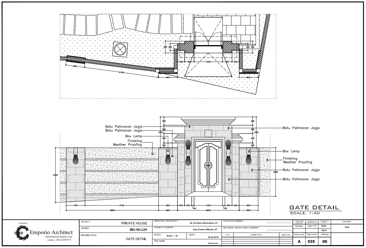
Gate details elaborate drawing sections and gate’s front view in a larger scale, which contains every information regarding its dimension, proportion, shape, type, and color of the material for the finishing, which results in a clearer and detailed gate display.
B. Mechanical, Electrical & Plumbing (MEP) Technical Drawing
1. Electrical Plan (Lamp & Light Switch Points) of Each Floor
%20Tiap%20Lantai.png)
The lamp & Light Switch points plan elaborates each floor’s layout, along with the symbols that symbolize the plan points of each lamp & Light Switch placement on the basement, first floor, second floor, and so on, all the way to the ceiling with the cable lane.
Not only does it cover the lamp & light switch placement, but also the information regarding the number of lamp points that ease up the planning and lamp purchasing during construction.
2. Electrical Plan (Socket & AC Points) of Each Floor
%20Tiap%20Lantai.png)
The electrical plan of socket & AC points elaborates the layout of each floor with symbols that symbolize the plan points of socket and AC, along with the cable lane.
Not only does it cover the lamp and light switch placement, but also the information regarding the number of sockets that ease up the construction process in the later day.
Generally, the electrical plan is combined together to show the overall needs and placement points of the lamps, sockets, light switches, and AC of 1 sheet for each floor.
3. Lightning Rod Plan
.png)
The lightning rod plan elaborates the sky view of the building, along with the lightning rod installation plan on the roof and its lane.
4. Lightning Rod Details
.png)
The lightning rod details elaborate the lightning rod system on a larger scale that includes the shape, size, material, and others in clearer and detailed information.
5. Clean Water & Water Heater Installation Plan (of Each Floor)
.png)
The clean water & water heater installation plan elaborates the floor layout with symbols that symbolize the placement points of the clean water & water heater, along with the pipe lane.
The goal is for every floor to have clean water & water heater installation plan of its own. If the project doesn’t require a water heater, the plan will only include the clean water system.
6. Dirty Water, Water Wastage, & Rain Water Plan (of Each Floor)
.png)
Dirty water, water wastage, & rainwater installation plan elaborates the floor layout with symbols that symbolize that placement points and the pipe lane of the dirty water, water wastage, & rainwater of each floor from the basement to the roof.
7. Septic Tank/Bio Tank Details
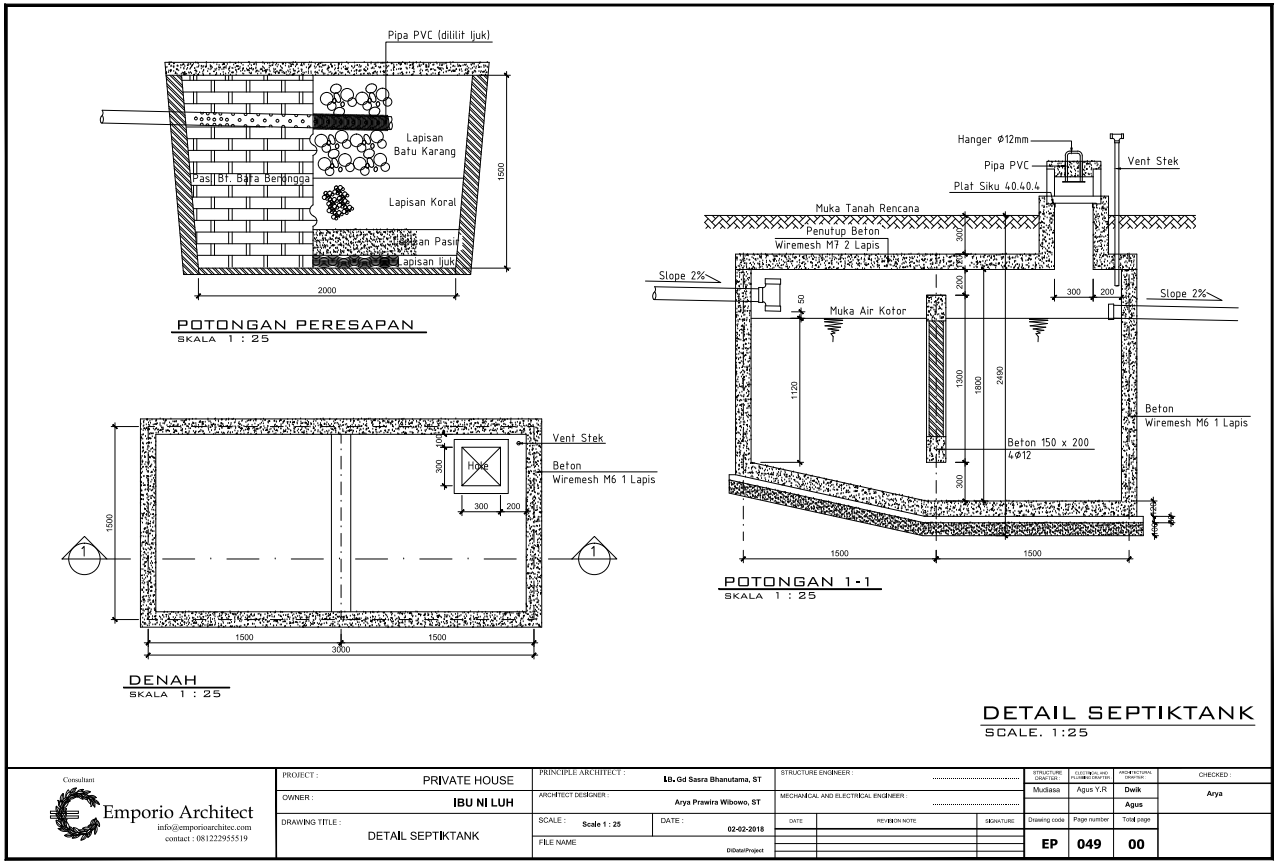
Septic tank/bio tank details elaborate the septic tank/bio tank sections on a larger scale to clarify the shape, display, layer, material, and dimensional size for a clearer image.
8. Control Box & Bio Pore Details
.png)
The permeation detail (control box & bio pore) elaborates the layout and sections of the absorption on a larger scale to form a shape, composition, material type, and dimension for a clearer and more detailed image.
9. Ground Tank Details
.png)
The ground tank details elaborate the ground tank sketch on a larger scale to create a clearer image with the details of its shape, size, material, and pipe lane.
C. Structural Technical Drawing
1. Foot Plate Foundation / Bored Pile
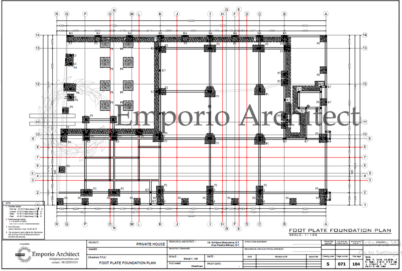
The footplate foundation / bored pile elaborates the floor layout without stating the name of the spaces, elevation, and furniture. The emphasized factor in this foundation plan is the placement of the foundations, whether it’s the foot plat or bored pile, including the gate walls that surround the land, pond/pool, gazebos, and other facilities.
2. River Stone Foundation
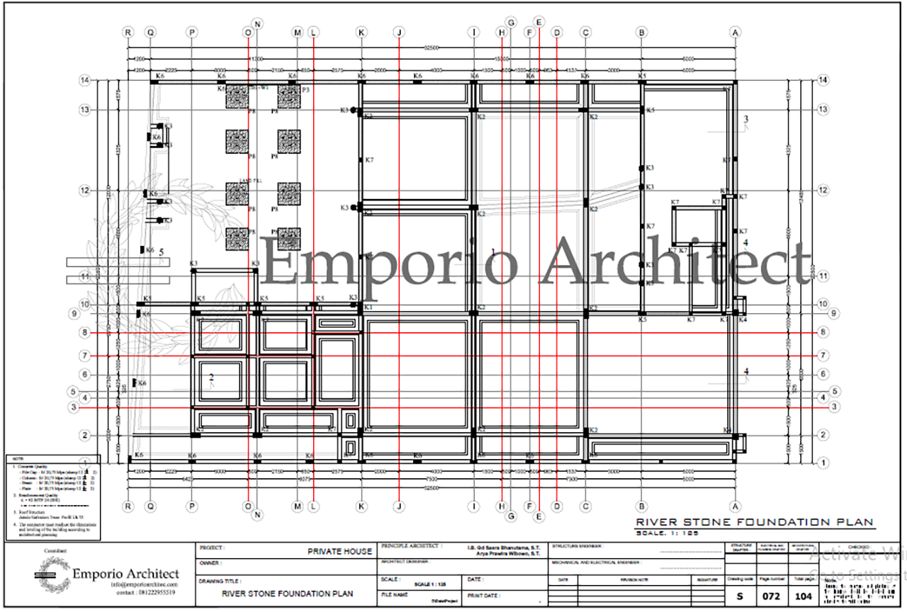
The river stone foundation plan elaborates the floor layout without stating the name of the spaces, elevation, and furniture. The emphasized factor in this river stone foundation plan is the placement of the river stone foundations of the building, outer gate that surrounds the land, pond/pool, gazebos, and other facilities.
3. Tie Beam and Ground Floor Column
.png)
Tie Beam and column layout elaborate the layout of every floor without stating the name of the spaces and furniture with the placement of tie beam and column in the house. The tie beam and column drawing usually each contains 1 sheet of the basement and ground floor of the building.
4. Beam and Column Plan (of Each Floor)
.png)
Beam and column layout plan elaborate the layout of every floor without furniture with the placement of beam and column in the building. The beam and column drawing usually each contains 1 sheet of each floor of the building.
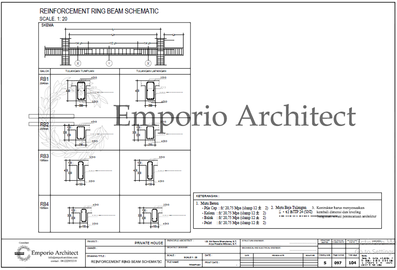
5. Roof Beam or Gutter Plan
.png)
The roof beam or gutter plan looks similar to the previous drawing, where it elaborates the beam placement on the roof of the building, along with the type and size.
6. Floor Slab Reinforcement Layout Plan
.png)
The floor slab layout plan elaborates the slab/floor plate reinforcement in the building, which functions to distribute the load to the main structure of the building.
The slab reinforcement plan also directs the placement of the floor slab reinforcement, the material used, and a clearer measurement.
7. Grid X Portal (1 Transverse Portal)
.png)
Grid X portal elaborates the main structure of the building that shows the main structure transverse sections. This drawing also refers to the building’s main structure entirely, the material used, elevation, and other foundations to the ceiling.
8. Grid Y Portal (1 Longitudinal Portal)
.png)
It has a similar function and displays with the grid X portal. The difference is the grid Y portal shows the longitudinal sections of the main building structure.
9. Foot Plate Foundation / Bored Pile Details
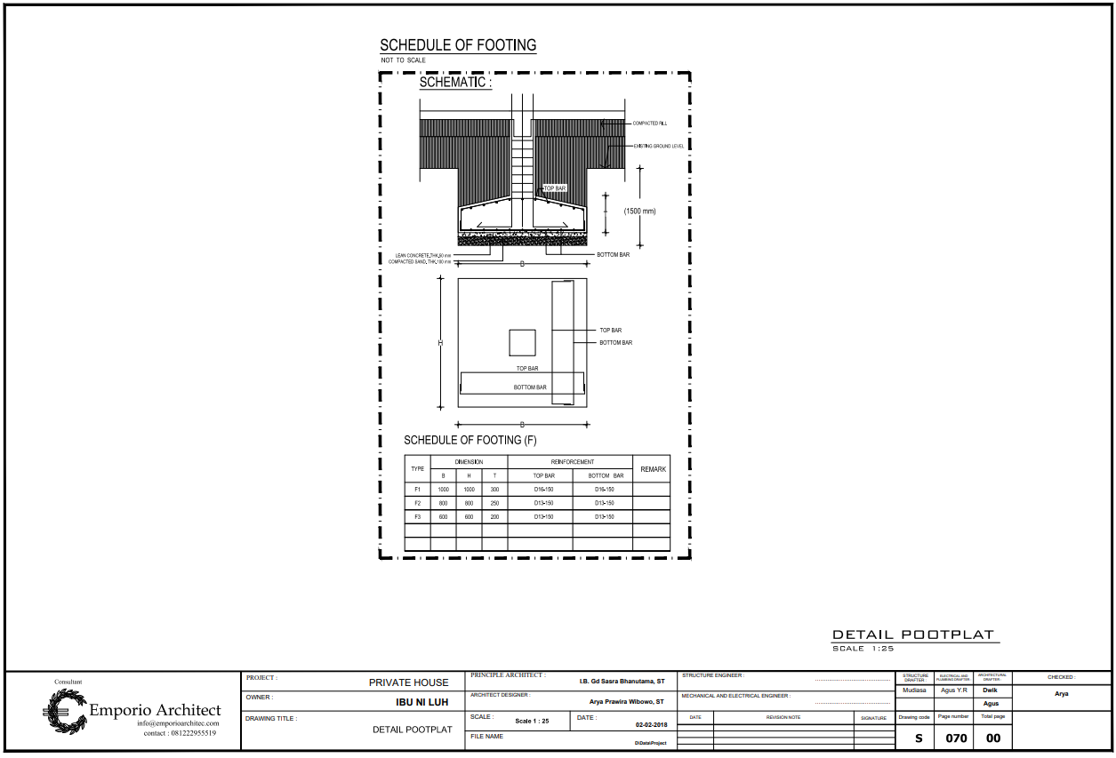
Displayed on a larger scale, footplate foundation / bored pile details elaborate the shape, composition, material used, and the foundation size in a clearer and more detailed drawing.
10. River Stone Foundation Details
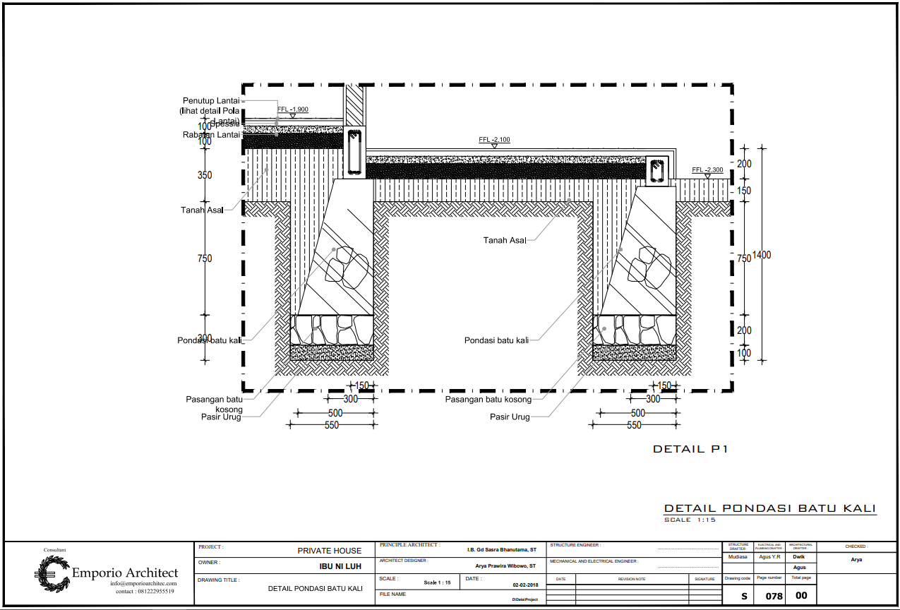
The river stone foundation details elaborate the part/composition of the river stone of the building, which has a larger scale for a clearer image. This drawing has the detail of the material type, composition/layer, and the size of every foundation.
11. Column Framing Details
.png)
The column framing detail elaborates every composed plate reinforcement or column framing of the main building structure.
12. Tie Beam Framing Detail
Tie beam framing detail elaborates the tie beam reinforcement details of the building. Generally, the technical drawing only contains 1 sheet with the detail of sloof work, columns, tie beam, and ring beam that have been structurally composed to the main building main structure.
13. Beam Framing Details
.png)
Beam framing details elaborate every detail regarding steel reinforcement or composed beam framing of the building’s main structure.
14. IWF Steel Structure Details (Light Roof Steel Structure Excluded / By Vendor)
.png)
.png)
IWF (Wide Flange) steel structure details elaborate the shape, display, information, composition, and material used on the IWF steel structure of the building. The steel structure details are created on a larger scale for a clearer image of every part.
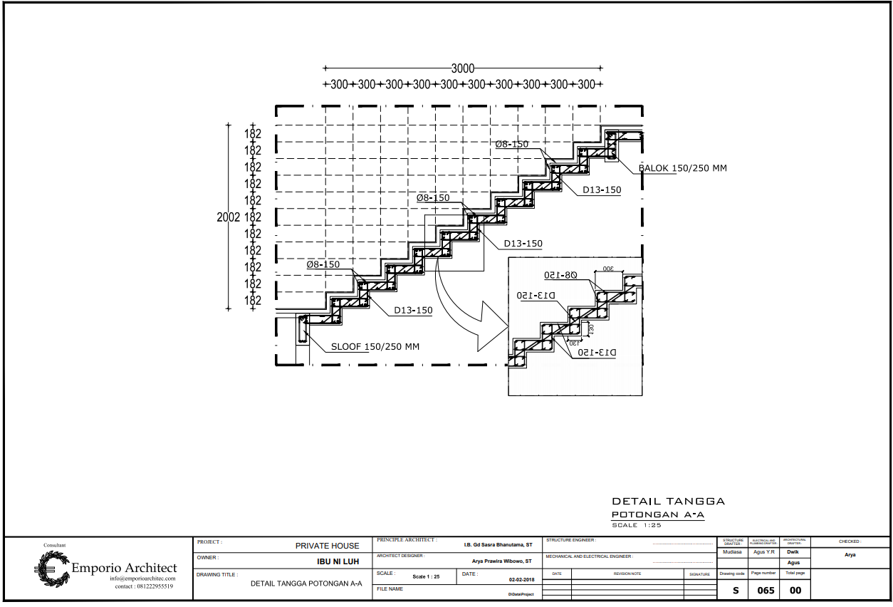
15. Stairs Layout, Sections, and Structural Reinforcement Details
.png)
.png)
.png)
The stairs layout, sections, and structural reinforcement details elaborate the layout display, sections, and every reinforcement detail regarding the stairs structure of the building with its measurement, elevation, composition, and the material used in a detailed version.
Generally, every work drawing book contains several sheets of the layout plan, sections, and structural reinforcement for every type of stairs on every floor of the building.
16. Swimming Pool Layout, Sections, and Structural Reinforcement Details
.png)
.png)
.png)
Swimming pool layout, sections, and structural reinforcement details elaborate the details of the swimming pool, including the layout shape, sections, and the reinforcement in a detailed drawing
Created on a larger scale, every composition, layer, measurement, elevation, and material used will be in a clearer image, from the foundation, framing, and all the way to its surface. This drawing is included in the building is facilitated by a swimming pool.
17. Pond Layout, Sections, and Structural Reinforcement Details
.png)
Pond layout, sections, and structural reinforcement details elaborate every part of the pond, including the layout, sections, and structural reinforcement in detail.
Every detail of the composition, layer, measurement, elevation, and material used for the pond will be presented in a clearer image, from the foundation, framing, and its surface because the drawings are created on a larger scale.
The pond’s layout plan, sections, and structural reinforcement will not be created if the building does not have any water pond.
Those are the technical drawings to plan a house design planning that are commonly needed in technical drawing books with their respective functions. Now that you know the function of each design drawing and digest the importance of each design drawing as a guide to building a house, you are now ready to start the design journey with Emporio Architect to make your dream house come to a realization!

If you have any questions, please consult with us.


